+86-18633235200
The spray layer in desulfurization towers currently primarily adopts two material and structural configurations:
1) Full FRP construction: Due to the material characteristics of FRP, this design requires support beams beneath the spray pipes.
The spray layer in desulfurization towers
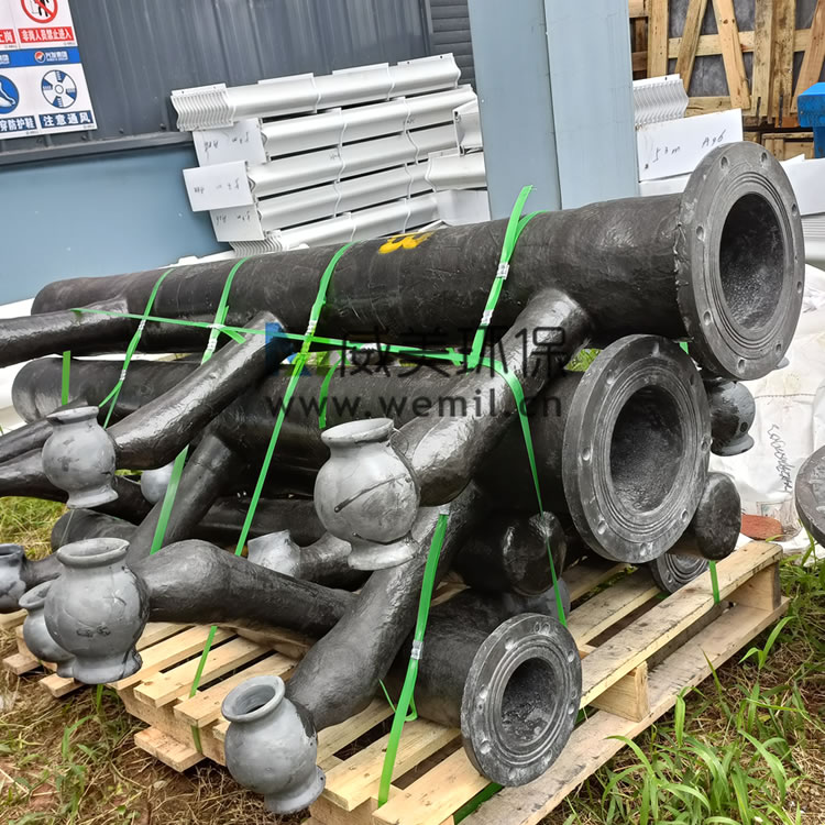
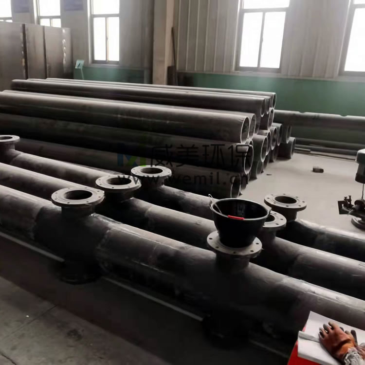
2) Carbon steel main pipes with rubber lining (internal and external), paired with FRP branch pipes. The main and branch pipes are connected via flanges. The main pipes, utilizing equal-diameter steel tubes, function as support beams, eliminating the need for additional underpinning structures.
The spray piping network in desulfurization towers distributes slurry through nozzles arranged along the pipes, generating mist-like droplets to absorb SO? from flue gas. The pipes must demonstrate abrasion and corrosion resistance both internally and externally, with surfaces capable of withstanding slurry erosion. The design prioritizes optimal nozzle arrangement to ensure uniform slurry distribution within the tower, avoiding irregular spraying patterns.
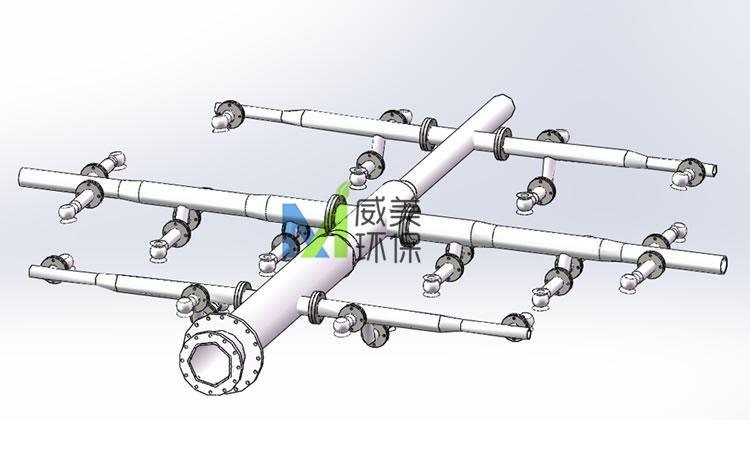
Spray Layer Layout Diagram for Desulfurization Tower
The spray layer in desulfurization towers, also referred to as liquid distributors, consists of spray pipes and nozzles. Slurry is evenly distributed through the spray pipes to each nozzle, where it is dispersed and thoroughly contacts the counter-flowing flue gas, facilitating the absorption of SO? pollutants.
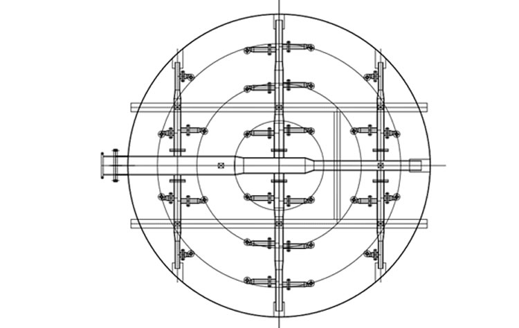
Spray Layer Layout Diagram for Desulfurization Tower
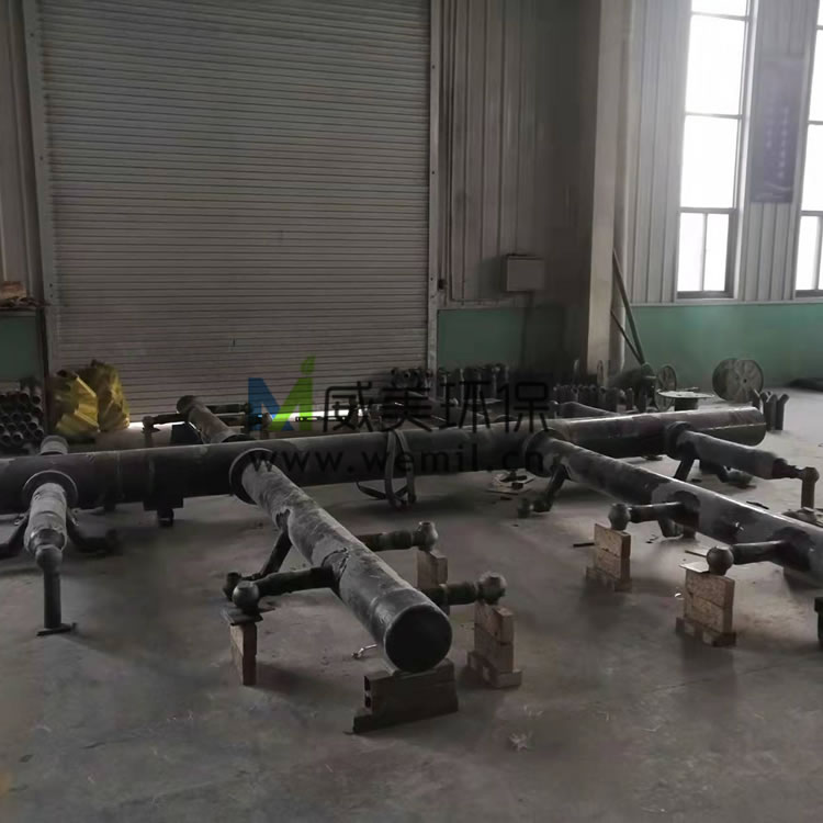
Spray Layer for Desulfurization Tower